Have you ever wondered about the technologies behind the devices we use daily? How do these electronic marvels function and become more compact with each passing year? One key component in modern electronics is the Flexible Printed Circuit Board (FPCB). In this blog post, we’ll dive deep into the world of FPCBs, covering everything you need to know.
FPCBs are innovative circuit boards that allow for flexible and lightweight electronic designs. They have become increasingly popular due to their adaptability, enabling the creation of smaller, more powerful devices. So, let’s explore the ins and outs of FPCBs together and discover why they’re so important in today’s electronics landscape.
1. History & Overview of FPCB
The history of FPCBs began in the early 20th century when the telephone industry required flexible electric circuits. In 1903, German inventor Albert Hanson filed the first patent for a flexible flat cable. Early methods involved paraffin-coated paper and Edison’s cellulose gum-coated linen. By the 1940s, photo-etched flexible circuits emerged, leading to their widespread use in military and aerospace applications during the 1950s. The development of flexible silicon technology allowed for semiconductors on flexible materials, and by the 1980s, FPCBs became a standard component in consumer electronics such as calculators, cameras, and computers, benefiting industries like aviation, medicine, and consumer electronics.
2. What Is FPCB?
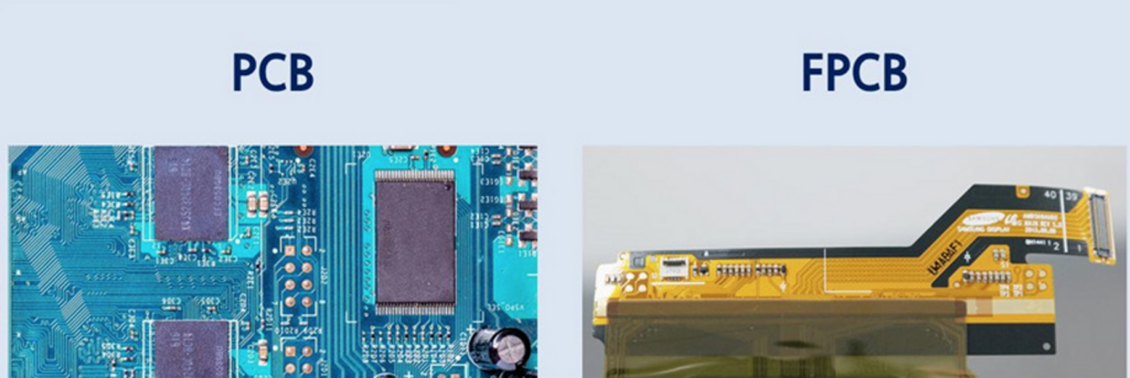
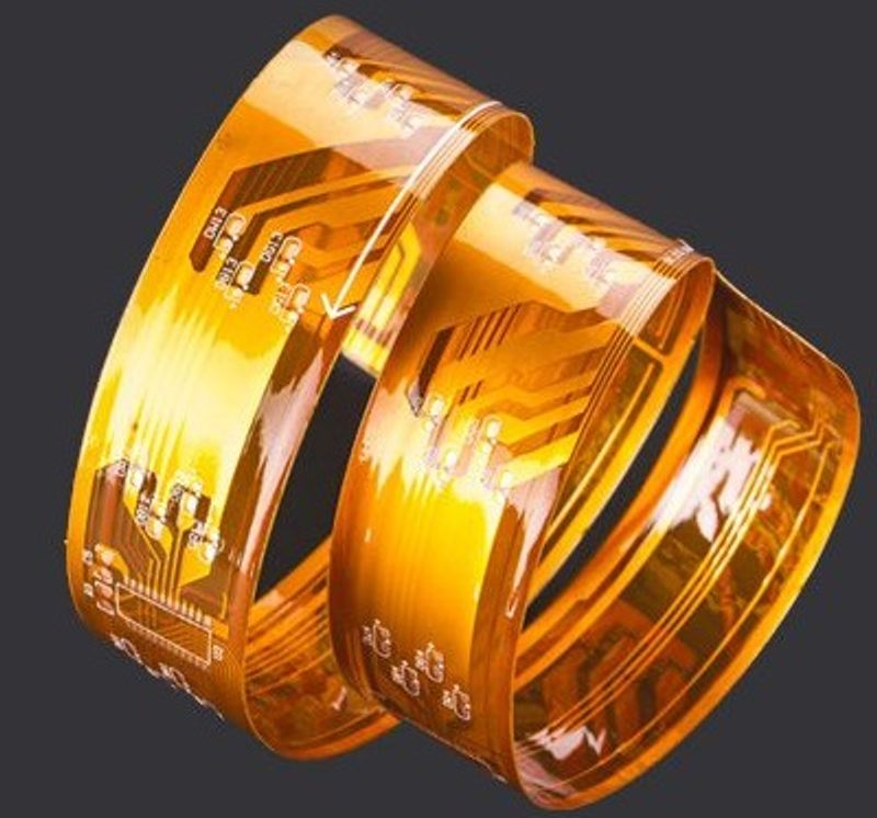
An FPCB, or Flexible Printed Circuit Board, is made from flexible materials like polyimide. This allows it to bend and adapt to compact spaces or irregular shapes. Unlike traditional rigid PCBs, FPCBs offer lighter, thinner, and more compact electronic devices due to differences in design, manufacturing, and materials.
Modern manufacturing techniques for FPCBs use photolithography or laser imaging to create patterns. They attach metal traces to dielectric materials such as polyimide. The thickness of metal and dielectric layers, as well as methods for connecting metals to substrates, differ from regular PCBs.
FPCBs need a protective layer over copper to prevent oxidation. They also use dielectric materials to avoid short circuits and oxidation within the circuitry.
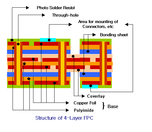
3. Structure of FPCB
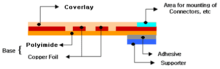
The structure of an FPCB typically consists of the following layers:
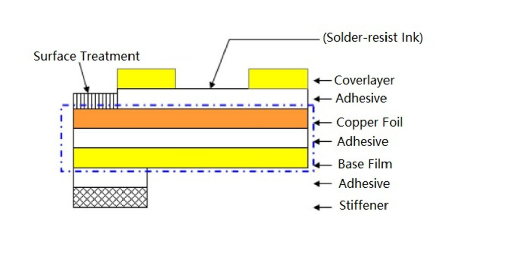
- Flexible substrate: This is the base layer, usually made of polyimide, which provides mechanical support and flexibility.It forms the foundation for the other layers of the FPCB.
- Adhesive: The adhesive layer is responsible for bonding the flexible substrate, copper conductor, and dielectric layers together. It is crucial in maintaining the overall flexibility of the FPCB, and it is generally made of a flexible material like acrylic or epoxy.
- Copper conductor/Foil: The copper conductor layer contains the actual circuitry of the FPCB. Copper is typically used for its high electrical conductivity, flexibility, and reliability. The circuitry is etched onto the flexible substrate using a chemical process or by using an additive process that builds up the copper traces on the substrate.
- Dielectric layer: The dielectric layer is an insulating layer that prevents electrical shorts between the conductive layers. It is usually made of a thin layer of polyimide or another insulating material that is compatible with the flexible substrate. The dielectric layer’s thickness is determined by the required electrical performance and isolation between the conductive layers.
- Coverlay or solder mask: This protective layer shields the conductive traces from environmental factors like moisture, dust, and contaminants, and it provides insulation between the conductive layers and other components. The coverlay is typically made of a thin, flexible film such as polyimide, while the solder mask is a liquid or dry film that is applied to the surface of the FPCB and then hardened.
4. The Manufacturing Process of FPCB
The manufacturing process of FPCBs is similar to that of rigid PCBs, with some key differences to accommodate the flexible nature of the materials used.
The steps involved are:
- Design: The FPCB layout is created using specialized software, taking into consideration the required flexibility and other design constraints.
- Substrate preparation: The flexible substrate, typically polyimide, is cleaned and prepared for the application of copper.
- Copper lamination: A thin layer of copper is laminated onto the substrate using heat and pressure.
- Photolithography: A photosensitive resist is applied to the copper layer, and the desired circuit pattern is transferred onto it using a photomask and UV light.
- Etching: The exposed copper is etched away, leaving behind the circuit pattern.
- Dielectric and coverlay application: The dielectric layer and coverlay are applied to protect the circuitry and provide insulation.
- Drilling and plating: Holes are drilled for vias and through-hole components, and then plated with copper to ensure electrical connectivity between layers.
- Component assembly: Electronic components are soldered onto the FPCB, either manually or using automated machinery.
- Inspection and testing: The assembled FPCB is inspected for defects and tested to ensure proper functionality.
5. Materials Used for Making FPCB
The primary materials used in the manufacture of FPCBs include:
- Flexible substrates: Commonly used materials include polyimide, polyester, and liquid crystal polymer (LCP).
- Conductive materials: Copper is the most widely used conductor, while other options like silver ink and conductive polymers are also available.
- Adhesives: Acrylic and epoxy adhesives are typically used to bond the layers of an FPCB.
- Dielectric materials: Flexible dielectric materials like polyimide and polyester films are used for insulation.
- Coverlay and solder mask materials: Flexible solder masks and polyimide coverlays are used to protect the circuitry and provide insulation.
6. Types of FPCB
There are several types of FPCBs, including:
- Single-sided FPCBs: These have one layer of conductive traces on a single side of the substrate.
- Double-sided FPCBs: These have conductive traces on both sides of the substrate, with vias providing interconnections between the layers.
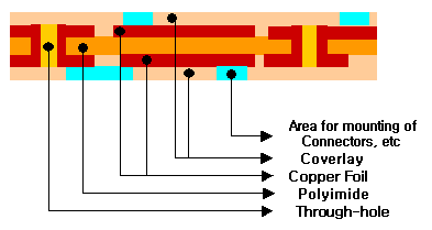
- Multilayer FPCBs: These consist of three or more layers of conductive traces, separated by insulating layers and interconnected by vias.
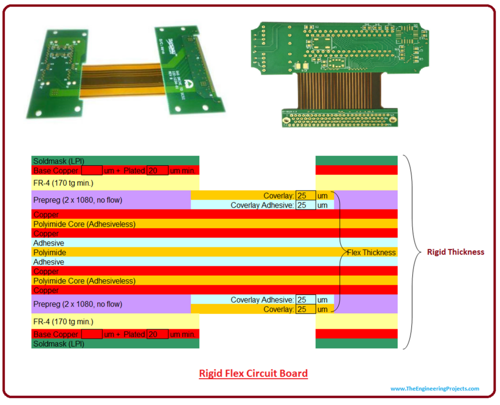
- Rigid-flex FPCBs: These are a hybrid of rigid and flexible PCBs, combining the benefits of both types. They typically consist of multiple flexible layers joined to rigid sections.
7. FPCB Applications
FPCBs have a wide range of applications across various industries, such as:
- Consumer electronics: Smartphones, tablets, laptops, cameras, and wearables all utilize FPCBs to achieve compact and lightweight designs.
- Medical devices: FPCBs are used in devices like hearing aids, implantable devices, and diagnostic equipment due to their flexibility and biocompatibility.
- Aerospace and defense: The lightweight and high-reliability characteristics of FPCBs make them ideal for use in satellites, avionics, and military equipment.
- Automotive: FPCBs are used in various automotive applications, including infotainment systems, sensors, and lighting.
- Industrial: FPCBs are utilized in robotics, control systems, and other industrial equipment where space and weight constraints are critical.
8. The Importance of FPCB
FPCBs play a crucial role in modern electronics due to their many advantages, such as:
- Design flexibility: FPCBs can be bent, folded, and twisted to fit into tight spaces and conform to complex shapes.
- Lightweight and compact: FPCBs are lighter and thinner than rigid PCBs, making them ideal for portable and space-constrained devices.
- High reliability: The flexible nature of FPCBs makes them resistant to vibration and shock, increasing their reliability in harsh environments.
- Improved thermal performance: FPCBs dissipate heat more efficiently than rigid PCBs, leading to better thermal management and longer component lifespans.
9. Challenges and Cost Considerations of FPCB
While FPCBs offer many benefits, there are also challenges and cost considerations, such as:
- Higher production costs: The materials and manufacturing processes for FPCBs can be more expensive than those for rigid PCBs.
- Design complexity: The flexibility of FPCBs introduces additional design constraints that require careful consideration.
- Durability concerns: Although FPCBs are more resistant to shock and vibration, they may be more susceptible to damage from repeated bending or flexing over time.
- Assembly challenges: The flexible nature of FPCBs can make component assembly more difficult, requiring specialized equipment and techniques.
10. Advanced Features of FPCB
FPCBs continue to evolve, incorporating advanced features to meet the demands of modern electronics:
- Embedded components: Passive components, such as resistors and capacitors, can be embedded within the layers of an FPCB to save space and improve performance.
- High-density interconnect (HDI): HDI technology allows for smaller vias and more closely spaced traces, increasing the interconnect density and enabling the design of smaller and more complex FPCBs.
- Stretchable circuits: Researchers are developing stretchable FPCBs that can expand and contract without losing functionality, opening up new possibilities for wearable electronics and other applications.
11. Benefits of Using FPCB
Some of the key benefits of using FPCBs in electronic devices include:
- Design versatility: FPCBs enable designers to create more compact, lightweight, and innovative products.
- Improved performance: FPCBs can offer better signal integrity and thermal performance than traditional rigid PCBs.
- Reliability: The flexible nature of FPCBs makes them more resistant to vibration and shock, increasing their reliability in harsh environments.
- Space and weight savings: FPCBs can help reduce the overall size and weight of electronic devices, making them more portable and user-friendly.
12. Drawbacks of Using FPCB
Despite their many advantages, there are some drawbacks to using FPCBs:
- Higher costs: The materials and manufacturing processes for FPCBs can be more expensive than those for rigid PCBs.
- Design challenges: Designing FPCBs can be more complex due to the need to account for flexibility and other constraints.
- Durability concerns: FPCBs may be more susceptible to damage from repeated bending or flexing, which can limit their lifespan in certain applications.
13. Differences Between Rigid PCBs and Flexible PCBs
There are several key differences between rigid PCBs and FPCBs:
- Flexibility: Rigid PCBs are made from rigid materials like FR4, while FPCBs use flexible materials like polyimide.
- Weight and thickness: FPCBs are generally thinner and lighter than rigid PCBs.
- Design complexity: FPCBs can be more challenging to design due to the need to account for flexibility and other constraints.
- Cost: FPCBs can be more expensive to manufacture than rigid PCBs, primarily due to the materials used and specialized manufacturing processes.
14. Importance of FPCB in LED Strips
FPCBs play a vital role in the design and functionality of LED strips. They provide the following benefits:
- Flexibility: FPCBs enable LED strips to be bent and shaped to conform to various surfaces and applications.
- Lightweight and thin: FPCBs contribute to the low weight and slim profile of LED strips, making them easy to install and unobtrusive.
- Efficient heat dissipation: FPCBs can help dissipate heat generated by the LEDs, prolonging their lifespan and maintaining performance.
15. F.A.Qs
16. Summary
FPCBs have become an integral part of modern electronics, enabling the design of compact, lightweight, and innovative devices. By offering flexibility, improved performance, and high reliability, FPCBs have found applications across a wide range of industries, from consumer electronics to aerospace and medical devices. Despite the challenges and cost considerations, FPCBs continue to evolve, incorporating advanced features to meet the demands of today’s technology landscape.
In this comprehensive guide, we have covered the history, structure, manufacturing process, materials, types, applications, and importance of FPCBs. We have also discussed the challenges and cost considerations, advanced features, benefits, drawbacks, and differences between rigid PCBs and FPCBs. Armed with this knowledge, you are now well-equipped to understand and appreciate the critical role FPCBs play in the devices we use every day.
